
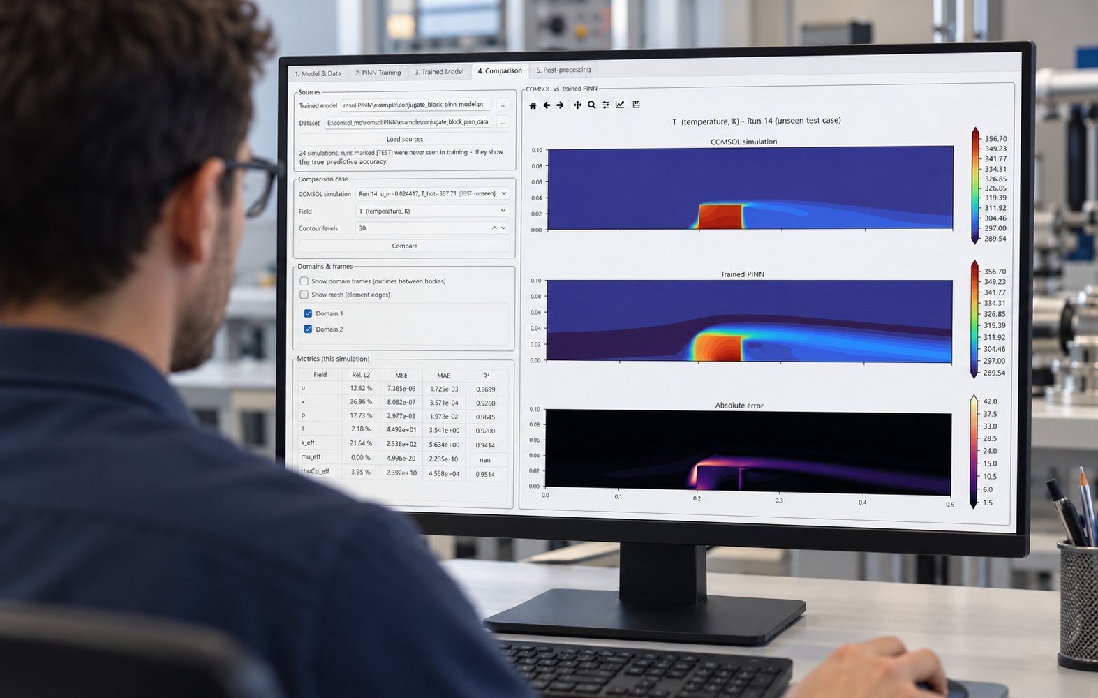
ASHRAE 127 CDU Addendum b turns liquid-to-liquid CDU work into a steady-state laboratory rating problem: define TCS and FWS, measure both loops, calculate net capacity, critical input power, CDU thermal efficiency, pressure drop, and energy balance, then report the rating conditions. It does not validate transient or field performance.
The February 27, 2026 update matters because a simulation model can now mirror a defined liquid cooling test standard. UL Solutions describes the new metrics and laboratory limits. ASHRAE Journal Podcast Episode 44 and the SC25 presentation explain the remaining engineering need: comparable capacity and hydraulic results across CDU designs.
What does ASHRAE 127 CDU Addendum b actually rate?
ASHRAE 127 CDU Addendum b rates a liquid-to-liquid, single-phase CDU at defined steady-state operating points. Section 3.1 defines the technology cooling system, or TCS, and facility water system, or FWS. Section 9.1 limits the method to a test facility where instrumentation is installed and load stability can be maintained.
Use the standard to compare steady-state capacity, power, efficiency, and hydraulic behavior. Do not use one compliant rating point to claim transient response, control stability, installation performance, or field behavior. Informative Appendix G separates those application tests from tests performed under the standard.
The standard test points in Table 9-1 use 26°C FWS entering temperature and 30°C FWS leaving temperature. TCS entering temperature is 39.6°C at full capacity, 37.2°C at 75%, 34.8°C at 50%, and 32.4°C at 25%. These are test-plan anchors, not universal design conditions.
For broader system work, connect the CDU model to your data center cooling simulation so facility-side conditions remain explicit rather than hidden inside a rating.
Which inputs and outputs belong in your CDU model?
Map every Addendum b quantity to a named model variable, a calculated output, or a test measurement. That separation prevents a simulated value from being mistaken for an instrument reading.
| Metric or concept | Addendum b clause | Simulation mapping | Test measurement or report |
|---|---|---|---|
| TCS and FWS | Section 3.1; Normative Appendix H, Table H-1 | Inputs: m_TCS and m_FWS in kg/s, fluid properties, inlet temperatures in °C, inlet pressures in kPa | Measure entering and leaving temperature, mass or volumetric flow, and pressure on both loops |
| CDU net capacity | Sections 3.1, 6.4.1.1–6.4.1.3, 10.1.2; Table 10-1 | Output Q_net in kW from mass flow, enthalpy or temperature difference | Report corrected net cooling capacity in kW at each operating point |
| Critical input power | Sections 3.1, 6.4.2.1–6.4.2.2, 10.1.3–10.1.4 | Output P_crit in kW from pumps, drives, controls, instrumentation, fans, and other critical devices | Measure CDU electrical input; list auxiliary power separately |
| CDU thermal efficiency | Sections 3.1, 6.4.3–6.4.3.1, 10.1.5; Table 10-1 | Output η_CDU = Q_FWS ÷ Q_TCS × 100% | Report heat absorbed by FWS divided by heat removed from TCS; keep COP separate |
| CDU thermal losses | Section 3.1; Section 10.1.11 and Table 10-1 | Output Q_loss in kW to ambient air, including convective and radiative loss terms | Report net heat rejection to space ambient in kW |
| Hydraulic performance | Sections 3.1, 10.1.6.1–10.1.7; Appendix H | Outputs Δp_TCS and Δp_FWS in kPa, external head in kPa, and facility pumping power in kW | Measure pressure drop, flow in kg/s or L/min, and available TCS head |
| Energy balance | Sections 3.1, 6.5.1–6.5.1.1, 10.1.11–10.1.12; Table 10-1 | Output E_bal as a percentage residual over the complete CDU control volume | Report energy-balance percentage, all Q terms, fluid properties, and measurement statistics |
Use mass flow in kg/s as the solver-native quantity. If your test bench logs L/min, convert it with the measured fluid density before calculating Q_net. Store temperature in °C, pressure in kPa, capacity in kW, and power in kW so the model and report use one unit convention.
Which measurements control the result?
Section 7, Table 7-1 sets the measurement-system requirements. The limits matter most when the CDU temperature rise is small, because sensor uncertainty can become a large fraction of the calculated capacity.
- Fluid temperature: ±0.11°C accuracy with 0.005°C minimum resolution.
- Fluid mass flow: ±1.0% of reading, with four significant figures. The accuracy also applies to volumetric meters.
- Differential pressure: ±1.0% of reading, with three significant figures.
- Electrical power at ≤600 V: ±1.0% of full scale and ±2.0% of reading. Above 600 V: ±1.5% of full scale and ±2.5% of reading.
- Atmospheric pressure: ±1.0 kPa accuracy with 0.1 kPa resolution.
- Current and potential transformers: metering accuracy class 0.3 or better where used.
How should you run parallel ASHRAE 127 CDU cases?
Run a parameter sweep that varies flow, approach temperature, and facility-side conditions before you publish a rating. A single converged case proves only that one operating point solved.
In one Multi Optimization workflow, we ran 24 steady-state COMSOL cases with 8 parallel solver workers. Latin hypercube sampling varied TCS flow from 0.20 to 0.50 kg/s, approach temperature from 4°C to 10°C, and FWS entering temperature from 24°C to 30°C. Wall-clock time was 31 minutes. The worst energy-balance residual was 0.42%.
A simulation-to-test workflow with failure modes
- Define the TCS and FWS control volumes, fluid chemistry, and operating point. Failure mode: mixing facility-side heat rejection with CDU heat transfer makes the energy balance look better than it is.
- Create explicit inputs for m_TCS, m_FWS, inlet and outlet temperatures, pressures, density, specific heat, and critical power. Failure mode: using volumetric flow without updated density corrupts capacity when fluid temperature changes.
- Solve each case to steady state and retain time samples, not only the final field. Failure mode: numerical convergence can occur while the physical energy balance is still drifting.
- Calculate Q_net, Q_FWS, P_crit, η_CDU, Δp, Q_loss, and E_bal. Failure mode: omitting pump power or ambient heat loss hides a real residual.
- Report the operating conditions beside every result. Failure mode: a CDU passes at 0.35 kg/s and 26°C FWS inlet, then fails the required capacity or efficiency when flow, approach temperature, or facility-side temperature changes.
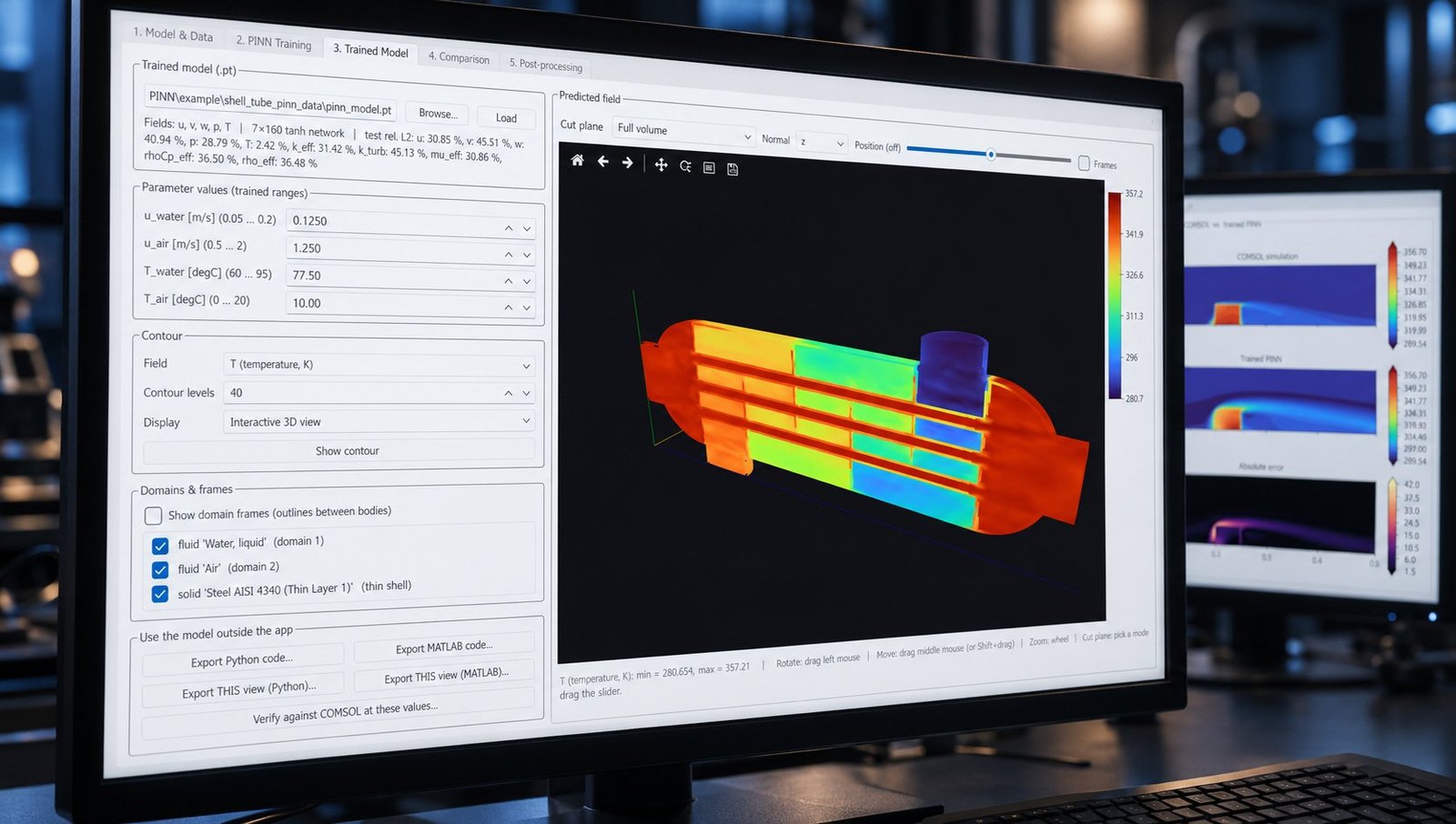
The COMSOL field can feed a PINN or other surrogate for wider coverage, but the surrogate must preserve the measured variables and residual checks. Our workflow also uses cfd simulation dataset coverage practices to identify sparse regions before optimization.
Why can a CDU pass one rating point and fail elsewhere?
The common failure mode is rating-point overfit. A CDU can meet Q_net and η_CDU at one flow and temperature combination, then miss capacity, pressure-drop, or energy-balance limits after the TCS flow changes or the FWS becomes warmer.
Flow changes alter Reynolds number, pump head, heat-transfer coefficient, and critical input power. Approach-temperature changes reduce the available driving temperature difference. Facility-side changes alter FWS heat rejection and may increase required pumping power. Addendum b gives you a consistent laboratory method, but it does not remove these dependencies.
Treat a rating as a coordinate in an operating envelope. Use the same model variables for 100%, 75%, 50%, 25%, and minimum-capacity cases, then compare the predicted outputs with measured means, standard deviations, and residuals. This is also where simulation helps you reduce data center pue without hiding CDU pump energy.
ASHRAE 127 CDU FAQ
Does Addendum b certify a field installation?
No. Section 9.1 requires a purpose-designed test facility with stable load and installed instrumentation. Informative Appendix G says application and field tests must not be presented as tests complying with the standard.
Is CDU thermal efficiency the same as COP?
No. Section 3.1 defines CDU thermal efficiency as FWS heat absorbed divided by TCS heat removed. COP in Section 6.4.3.1 relates cooling capacity to critical input power.
What should the report include besides capacity?
Report critical input power, efficiency, TCS head, FWS pressure drop, both loop flow rates, entering and leaving temperatures, fluid properties, energy balance, voltage balance, sample statistics, and the test duration. Sections 10.1.10–10.1.14 and Table 10-1 define the reporting structure.
Use Addendum b as a model contract
ASHRAE 127 CDU Addendum b is most useful when your simulation variables match the test bench variables. Define the loops, preserve the measurement accuracy, sweep the operating envelope, and report residuals beside every rating. For parallel COMSOL optimization, PINN surrogates, and data-center cooling workflows, see Multi Optimization software for parallel optimization and AI surrogate modeling.