
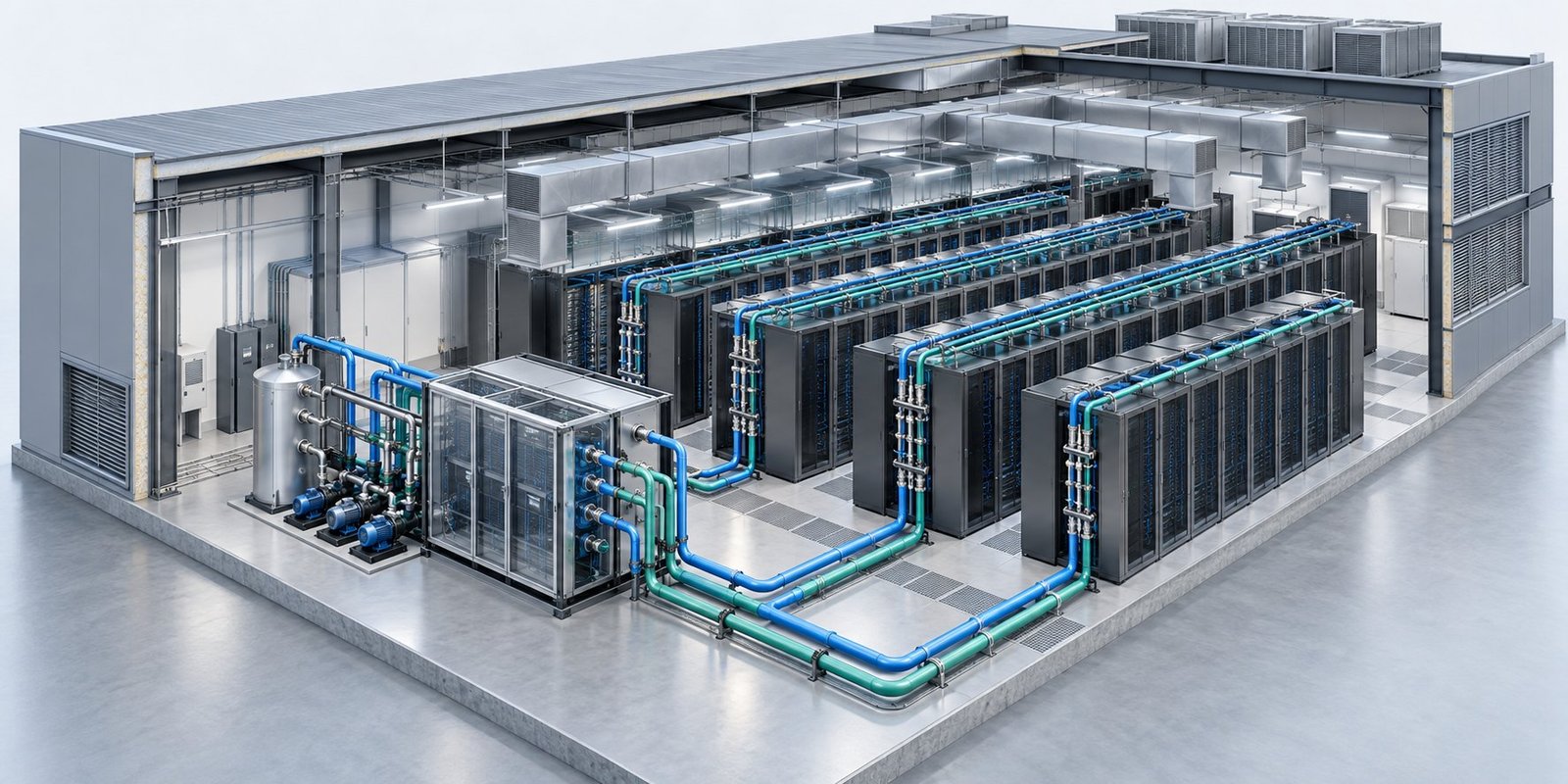
Data center cooling simulation is decision-ready only when your model ties measured inputs, chosen fidelity, required outputs, and failure evidence to a pass/fail rule. Specify rack power, airflow, temperatures, coolant flow, humidity, and failure duration before you run. Then test worst rack-inlet temperature, CDU ΔT, plant power, and time to thermal limit.
AI racks are changing the acceptance question. NVIDIA’s March 2026 Vera Rubin specification describes an NVL72 rack with 72 GPUs and 36 CPUs, 45°C warm-water cooling, and 45°C technology-loop water from a 41°C facility loop through a CDU. Your model must represent that path, not just a room air temperature.
What must a data center cooling simulation prove?
A credible model proves that its inputs, physical scope, outputs, and failure cases support a specific AI-facility decision. The pass/fail checklist must connect those four parts before you compare designs or approve a control strategy.
The ranking pages often describe model types without showing this connection. Use the following gate to expose missing evidence early.
| Checkpoint | Pass evidence | Decision use |
|---|---|---|
| Scope | Hall, racks, CDU, pumps, chillers, controls, and failure boundary are named | Shows which design decision the model can support |
| Input contract | Power, airflow, temperature, coolant, humidity, and duration use stated units | Prevents hidden conversions and undocumented assumptions |
| Fidelity | Air recirculation and rack heat paths are represented at the needed scale | Shows whether hot spots and liquid limits are explainable |
| Outputs | Worst rack-inlet temperature, CDU ΔT, pump power, chiller power, and time to thermal limit are reported | Connects simulation results to design limits |
| Failure evidence | Trigger, duration, thermal response, and recovery behavior are recorded | Supports an operational pass/fail decision |
See also: data center cooling software
Which inputs belong in the model contract?
Your model contract should state every thermal and hydraulic input with units, location, source, and time basis. If a value is inferred from an unnamed assumption, mark the model as incomplete before solving.
Minimum input register
- Rack power in kW, including the rack total and the split between air-cooled, direct-to-chip, and immersion loads.
- Airflow in m³/s for supply paths, rack inlets, exhaust paths, and any recirculation boundary.
- Supply and return temperatures in °C for the hall, rack path, air handlers, technology loop, and facility loop.
- Coolant flow in L/s through cold plates, immersion hardware, CDU branches, pumps, and the facility connection.
- Humidity and dew point, with relative humidity (%) and dew point in °C at the relevant air locations.
- Failure duration in minutes for a CDU pump trip, air-handler outage, facility-loop interruption, control fault, or other named event.
For NVIDIA’s Vera Rubin case, include the 45°C technology-loop supply, the 41°C facility-loop condition, the CDU heat exchange, and the 72-GPU, 36-CPU rack load. Do not collapse those values into one generic coolant temperature.
How much fidelity does mixed cooling require?
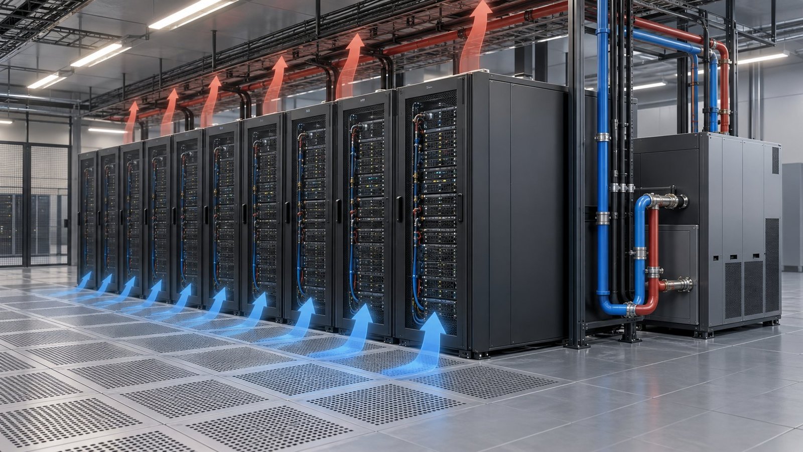
A mixed air and liquid cooling simulation needs separate hall airflow, rack thermal, and coolant-loop paths. An AI data center thermal model is not credible if it predicts rack inlet temperature without representing recirculation or liquid heat removal.
LBNL describes MOSTCOOL as a multi-objective toolkit for power, thermal management, cost, reliability, and availability. Its Modelica work couples air- and liquid-cooled systems with storage, waste heat, electrical systems, and controls. That coupling matters when a cooling decision changes plant power or failure response.
SHD Sim separates hall airflow and recirculation from rack-level thermal behavior. It uses conjugate heat transfer when solid thermal behavior matters, then a frozen-flow thermal pass after the flow field settles. Use that distinction to choose fidelity instead of applying one model class to every question.
| Model layer | Include | Use when |
|---|---|---|
| Hall airflow | Supply paths, return paths, containment, recirculation, and rack inlet locations | You need to locate hot spots or test a unit failure |
| Rack thermal path | Heat sources, rack-level air paths, cold plates, and immersion boundaries | You need to validate component or rack limits |
| CDU and coolant loop | Technology-loop and facility-loop temperatures, flow, exchange, pumps, and controls | You need CDU ΔT, pump power, or warm-water behavior |
| Dynamic failure | Control sequence, failure trigger, duration, thermal storage, and recovery | You need time to thermal limit or recovery evidence |
See also: CFD PINN Data Center Design for Cooling Optimization
Which outputs and failure tests decide the case?
The required outputs are the worst rack-inlet temperature, CDU ΔT, pump power, chiller power, and time to thermal limit. Set the acceptance limit for each output before the run, then retain the margin and failure trigger with the result.
For rack inlet temperature validation, compare the predicted worst rack and its location against the measured or specified limit. A single average inlet temperature can hide a localized failure.
- Worst rack-inlet temperature — identify the rack, time, operating state, and margin to the acceptance limit.
- CDU ΔT — report technology-loop inlet and outlet temperatures and the flow condition that produced the difference.
- Pump power — separate branch, CDU, and facility pumping where the design decision requires it.
- Chiller power — report the plant condition that removes the modeled heat.
- Time to thermal limit — state the failure trigger, duration in minutes, and first rack or component to reach the limit.
In Multi Optimization’s own example, approximately 68 components represented a mixed 30 kW air, 20 kW direct-to-chip, and 15 kW immersion case. The modeled result reached PUE 1.24. That example is useful because it keeps the load split, component count, and plant result in one decision model.
Run the failure sequence
- Run the normal operating case and save the worst rack, CDU ΔT, pump power, and chiller power. Failure mode: baseline has no forced outage and establishes the reference margin.
- Trip one named cooling element, such as a CDU pump or air-handling unit, and record the exact trigger time. Failure mode: loss of flow or loss of air distribution.
- Hold the failure for the specified duration in minutes while tracking rack inlet temperature and coolant temperatures. Failure mode: sustained cooling loss pushes a rack toward its thermal limit.
- Restore the failed element and record recovery time, peak temperature, and any rack that remains above its limit. Failure mode: delayed recovery or control instability after restoration.
- Mark the case pass or fail against predeclared limits. Failure mode: missing evidence, unnamed assumptions, or an output without a traceable input.
FAQ: How should you judge model credibility?
Is room temperature enough for AI rack decisions?
No. Room temperature cannot prove rack inlet behavior, CDU ΔT, liquid flow, or time to thermal limit. Model the rack path and the cooling boundary that can fail.
When should you use conjugate heat transfer?
Use conjugate heat transfer when solid conduction or solid-fluid interaction changes the result. After the flow field settles, a frozen-flow thermal pass can answer temperature-only questions more efficiently.
What makes a model pass or fail?
A model passes when every required input has units, every output has an acceptance limit, and each failure case records its trigger, duration, thermal response, and recovery. Missing traceability is a failure.
What should you approve before using the model?
Approve the model only after you can trace each decision from rack power and airflow to thermal response, plant power, and failure duration. Multi Optimization Admin applies this scope to data center software decisions and documents the result in the data center cooling simulation software workflow.