
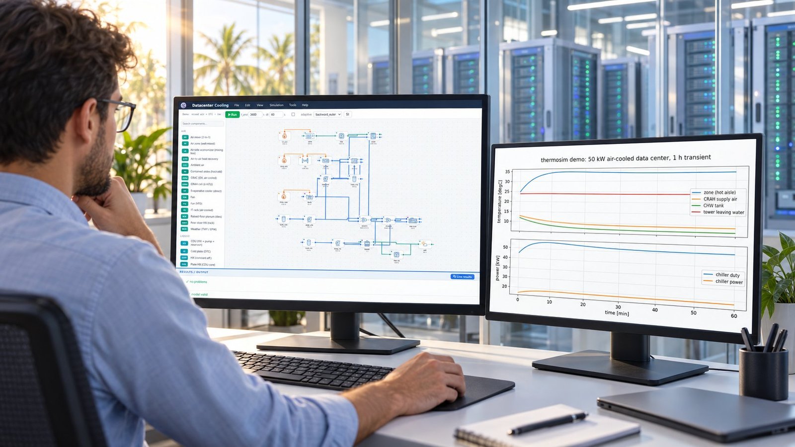
AI data center cooling standards become useful when you translate clauses into model variables and acceptance tests. SS 726:2026 defines the tropical liquid-cooling scope; Multi Optimization turns it into a parallel run matrix for coolant temperature, flow, CDU capacity, chip temperature, PUE, and WUE.
The missing step in most standards summaries is measurable implementation. This guide maps SS 726:2026’s lifecycle requirements to simulation inputs, outputs, failure modes, and a recorded 50 kW transient result.
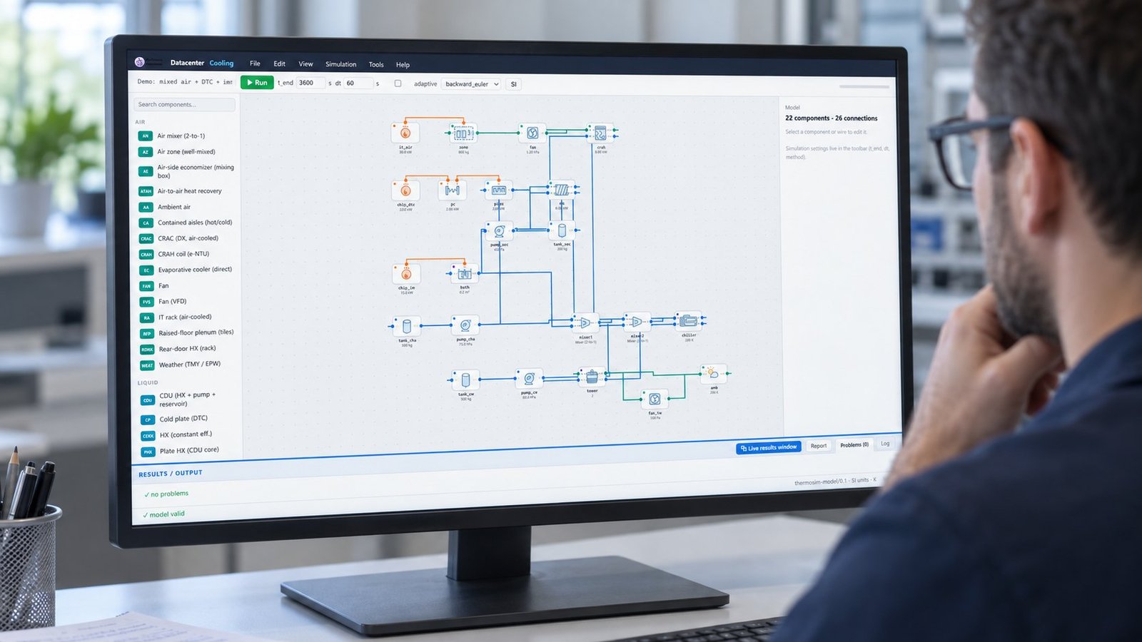
Why do AI data center cooling standards matter now?
SS 726:2026 matters because it is a 70-page Singapore Standard organized around tropical liquid-cooled facility delivery, not only equipment selection. Singapore Standards eShop lists requirements and recommendations for planning, design, deployment, management, maintenance, sustainable-performance tracking, and risk management.
Enterprise Singapore says the standard was developed by IMDA and Enterprise Singapore through the Singapore Standards Council. The timing matches higher AI heat density, but the practical value is narrower: you can turn the standard’s lifecycle sections into design variables and acceptance outputs.
What does Clause 1, Scope, actually cover?
Clause 1 states: “This Singapore Standard provides requirements and recommendations for the deployment of liquid-cooled systems within data centres located in tropical climate zones.” It covers coolant that removes heat directly from CPUs, GPUs, and TPUs.
SS 726:2026 excludes rear-door systems and other indirect liquid cooling. It also excludes two-phase systems and hybrid single-phase/two-phase systems. That scope makes SS 726:2026 a direct-to-chip cooling standard for the model class it names.
Which SS 726:2026 clauses should your model test?
Use Clause 8 for pre-deployment and commissioning, Clause 9 for operations and maintenance, Clause 10 for risk management, and Clause 11 for sustainability indicators. Each clause should produce a recorded result, not only a narrative design note.
| SS 726:2026 clause | Put into the model | Acceptance output | Failure mode / use when |
|---|---|---|---|
| 5–7: conditions, facilities, equipment | Ambient boundary, coolant type, CDU size, pump curve, rack heat load | Stable temperatures and adequate heat-removal margin | Use during concept design; fail if the CDU saturates or flow becomes unstable |
| 8: pre-deployment and commissioning | Startup sequence, valve states, flow ramp, control limits, sensor locations | Pass/fail commissioning envelope and time to stable operation | Use before handover; fail on trapped air, insufficient flow, or control oscillation |
| 9: operations and maintenance | Part-load schedule, filter fouling, pump degradation, coolant temperature drift | Temperature, pressure, power, and alarm trends over time | Use for maintenance planning; fail when degradation breaches the operating margin |
| 10: risk management | Leak, loss of flow, CDU fault, sensor failure, thermal runaway scenarios | Maximum chip temperature and controlled shutdown response | Use for hazard review; fail when a single fault exceeds the chip limit |
| 11: sustainability indicators | IT load, facility power, water use, heat rejection, operating hours | PUE, WUE, and sustainable-performance trend | Use for reporting and comparison; fail when the design misses the project target |
- Define the tropical boundary and IT load before optimization. Failure mode: an unrealistic ambient or load profile produces a false feasible design.
- Run commissioning transients with valve and pump states. Failure mode: a steady-state-only model hides startup flow loss.
- Inject maintenance degradation into the operating schedule. Failure mode: a clean-component model overstates end-of-life performance.
- Run leak, CDU, and sensor faults as separate scenarios. Failure mode: the nominal design passes while a single fault drives chip temperature beyond the limit.
- Report PUE and WUE with the same time window as thermal results. Failure mode: a short favorable window conceals sustained energy or water penalties.
How does SS 726:2026 compare with other AI cooling guidance?
SS 726:2026 gives you a tropical liquid-cooling scope and lifecycle structure. The PNNL/ASHRAE/NEMA AI Data Center Energy Performance Framework is broader and explicitly non-mandatory, while ITU-T L.1327 provides a general component-and-scenario selection method.
| Framework | Primary purpose | What you model | Use when |
|---|---|---|---|
| SS 726:2026 | Tropical liquid-cooled facility requirements and recommendations | Direct heat removal, commissioning, operation, maintenance, risk, and sustainability | Use for a Singapore or comparable tropical liquid-cooling project |
| PNNL/ASHRAE/NEMA AI Data Center Energy Performance Framework | Guiding principles for planning, design, commissioning, operation, retrofit, energy, and water | Facility-wide energy, water, resilience, grid interaction, and performance validation | Use for cross-functional AI facility planning; it does not establish mandatory requirements |
| ITU-T L.1327 | Cooling technology selection across multiple scenarios | Cooling components, performance factors, and application scenarios | Use early in technology screening before detailed acceptance simulation |
The distinction affects procurement. Use ITU-T L.1327 to structure the options, use the PNNL/ASHRAE/NEMA framework to widen facility objectives, then use SS 726:2026 to define the tropical liquid-cooling evidence package.
Which parameters belong in a parallel optimization matrix?
Start with six variables that connect thermal behavior to facility performance. The ranges below are a worked design space for screening, not limits stated by SS 726:2026.
| Parameter | Worked range | Role | Decision or use when |
|---|---|---|---|
| Coolant supply temperature (°C) | 25–40 | Controls heat-rejection opportunity and chip temperature | Increase when heat rejection allows it; reject if chip margin disappears |
| Coolant flow (kg/s) | 0.05–0.20 | Controls heat pickup and hydraulic power | Reduce only while maximum chip temperature remains within limit |
| CDU capacity (kW) | 50–150 | Sets rack-side heat-transfer headroom | Select the smallest capacity that survives peak load and fault margin |
| Maximum chip temperature (°C) | 70–85 | Thermal constraint | Use as a hard constraint during optimization and fault scenarios |
| PUE | 1.15–1.35 | Facility energy objective | Minimize after including pumps, CDUs, chillers, fans, and controls |
| WUE | 0.05–0.30 L/kWh | Water-use objective | Track with the same weather and operating schedule as PUE |
For a first screening pass, use NSGA-II with three objectives—minimum PUE, minimum WUE, and minimum maximum chip temperature—subject to CDU capacity and flow constraints. Multi Optimization can connect TRNSYS, EES, and COMSOL models, then replace expensive CFD evaluations with an AI or PINN surrogate after the dataset covers the operating envelope.
If your model contains high-cost flow and heat-transfer solves, the CFD PINN Data Center Design for Cooling Optimization workflow is the natural next step. Use cfd software coverage checks before trusting surrogate predictions outside the training region.
What did the measured parallel run show?
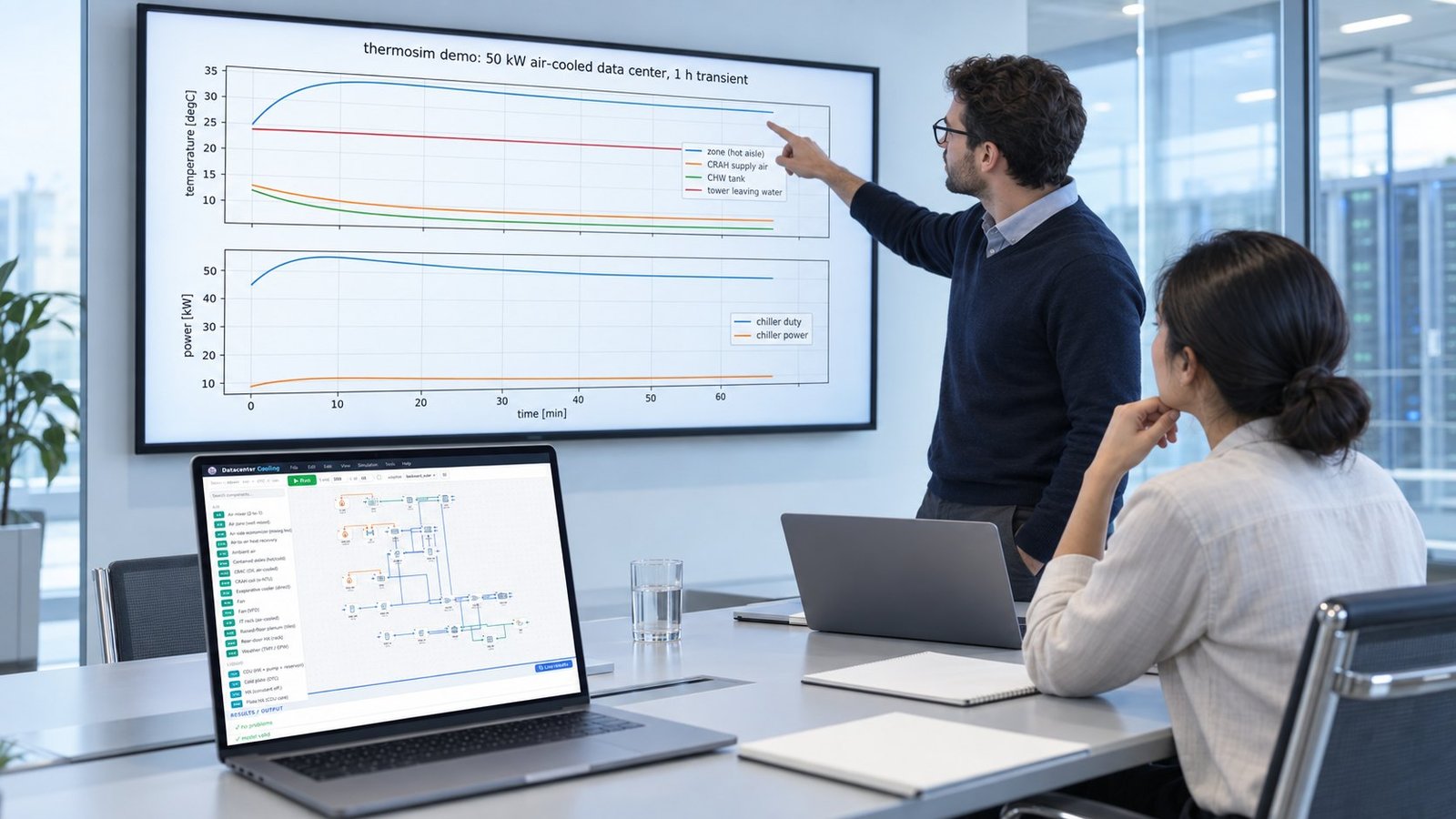
Our recorded parallel multi-objective reference run used a 50 kW air-cooled data center model under a tropical facility case. The one-hour transient began with a 25°C zone, 13°C CRAH supply, 12°C chilled-water tank, and 24°C tower leaving water.
The plotted result reached approximately 34°C in the zone, while CRAH supply fell toward 9°C and the chilled-water tank fell toward 7°C. Chiller duty rose from about 45.5 kW to 50 kW, while chiller power increased from roughly 9 kW to 10 kW. This is an internal simulation result, not an SS 726:2026 pass/fail value.
The result shows why a single design point is insufficient. A facility can meet the IT heat load while its zone temperature, chiller duty, and water-related objectives move in opposite directions. For the broader energy trade-off, compare the run structure with How to Reduce Data Center PUE: Simulation-Driven Cooling Design.
Frequently asked questions about SS 726:2026
Is SS 726:2026 mandatory?
Singapore Standards are generally voluntary unless made mandatory by a regulatory authority or incorporated into a contract. The standard can still become a procurement requirement.
Does SS 726:2026 cover rear-door cooling?
No. Clause 1 excludes rear-door solutions and other indirect liquid-cooling systems. It also excludes two-phase and hybrid single-phase/two-phase systems.
Which clause numbers cover commissioning and risk?
The public preview lists Clause 8 as Pre-deployment and commissioning, Clause 9 as Operations and maintenance, Clause 10 as Risk management, and Clause 11 as Sustainability indicators. Check the licensed copy before using detailed wording contractually.
What should you export from the simulation?
Export boundary conditions, parameter values, time histories, maximum chip temperature, CDU loading, PUE, WUE, alarms, and fault-case outcomes. Keep the run ID and solver settings with every acceptance result.
Turn the standard into a cooling design decision
SS 726:2026 gives tropical liquid-cooling projects a defined scope and lifecycle checklist. Multi Optimization adds the measurable layer: parallel multi-objective runs, TRNSYS, EES, COMSOL, AI surrogate models, and traceable acceptance outputs. Use our data center cooling simulation workflow to connect those requirements to a model you can test, compare, and maintain.